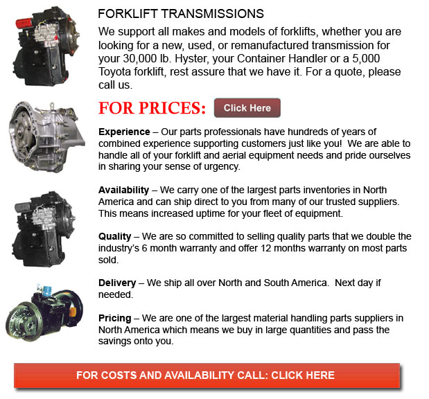
Transmissions for Forklifts - Using gear ratios, a gearbox or transmission offers speed and torque conversions from a rotating power source to another device. The term transmission refers to the entire drive train, including the clutch, final drive shafts, differential, gearbox and prop shaft. Transmissions are most frequently used in motor vehicles. The transmission adapts the productivity of the internal combustion engine in order to drive the wheels. These engines should operate at a high rate of rotational speed, something that is not suitable for stopping, starting or slower travel. The transmission increases torque in the process of reducing the higher engine speed to the slower wheel speed. Transmissions are even used on fixed machines, pedal bikes and anywhere rotational speed and rotational torque require change.
Single ratio transmissions exist, and they operate by changing the torque and speed of motor output. Numerous transmissions comprise multiple gear ratios and could switch between them as their speed changes. This gear switching could be carried out manually or automatically. Forward and reverse, or directional control, can be supplied as well.
The transmission in motor vehicles would typically attach to the engines crankshaft. The output travels through the driveshaft to one or more differentials in effect driving the wheels. A differential's main function is to change the rotational direction, even though, it can even supply gear reduction as well.
Power transmission torque converters as well as various hybrid configurations are other alternative instruments for speed and torque adaptation. Conventional gear/belt transmissions are not the only device offered.
The simplest of transmissions are simply called gearboxes and they provide gear reductions in conjunction with right angle change in the direction of the shaft. Sometimes these simple gearboxes are utilized on PTO machines or powered agricultural machinery. The axial PTO shaft is at odds with the common need for the driven shaft. This particular shaft is either vertical, or horizontally extending from one side of the implement to another, which depends on the piece of machine. Silage choppers and snow blowers are examples of much more complex machinery that have drives supplying output in various directions.
The type of gearbox used in a wind turbine is a lot more complicated and bigger as opposed to the PTO gearboxes found in farm equipment. These gearboxes convert the slow, high torque rotation of the turbine into the quicker rotation of the electrical generator. Weighing up to quite a few tons, and based on the size of the turbine, these gearboxes normally have 3 stages so as to achieve an overall gear ratio beginning from 40:1 to over 100:1. To be able to remain compact and to be able to supply the massive amount of torque of the turbine over more teeth of the low-speed shaft, the initial stage of the gearbox is normally a planetary gear. Endurance of these gearboxes has been a concern for some time.
![]() Click to Download the pdf
Click to Download the pdf
Forklift Parts
Lift Parts Express
TOLL FREE: 1-888-695-7994
LOCAL: 661-471-2086
2010 WEST AVENUE K 617
Lancaster, California
forkliftpartslancaster.com
Email Us
About Us


